1. Scope of Use
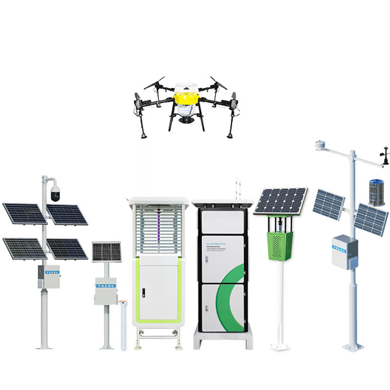
The support for various wireless communication antennas, lighting lamps, cameras, night vision devices, ordinary lightning rods and other equipment. It is especially applicable to the installation and use of various instruments with strong mobility and frequent movement. Such as the installation and installation of satellite signal receiving antennas, mobile radar lightning rods, etc.
Second, applicable environment
Working temperature: electric type-45℃~+55℃, manual type ±55℃. Maximum wind resistance30m/s( installation is solid and the pull line is in the state), flat and solid frequently moving various instruments of installation and use. Such as the installation and installation of satellite signal receiving antenna, mobile radar lightning rod, etc. Solid ground (indoor, outdoor), vehicle, square warehouse inside and outside of the installation, ship, offshore drilling platform installation.
Three, Technical Parameters
<table border="1" cellspacing="0" font-size:12px;width:668px;border:none;"="" style="box-sizing: inherit;font-family: 'Helvetica Neue', Helvetica, 'PingFang SC', 'Hiragino Sans GB', 'Microsoft YaHei', Arial, sans-serif;font-size: medium;text-wrap: wrap">
Product specifications | 10 meters | 12 meters | 15 meters | 20 meters | 30 meters |
Expand height | 10003mm | 12000mm | 15007mm | 20000mm | 30000mm |
Closed height | 2089mm | 2200mm | 2624mm | 2700mm | 3200mm |
Group material | Magnesium alloy | Magnesium alloy | Magnesium alloy | Magnesium alloy | Four-key management |
Product weight | 40KG | 50KG | 60KG | 61KG | 120KG |
Drive mode | Manual | Manual | Manual | Manual | Manual |
Wind resistance level | 8-10 level | 8-10 level | 8-10 level | 8-10 level | 8-10 level |
Group color | Army green | Army green | Army green | Army green | Army green |
Lightning rod | 0.5m special alloy lightning rod tip | Stainless steel lightning rod | 0.5m special alloy lightning rod tip | Stainless steel lightning rod | 0.5m special alloy lightning rod tip |
IV. Selection Conditions
1.Determine the maximum lift, closing height, load weight, and windward area of the load
2.Determine ground mounting, exterior mounting, or interior mounting
3.Determine the vertical or horizontal type of the electric model
4.Determine the power supply for the electric motor
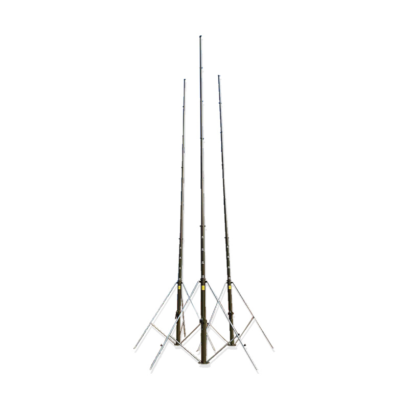
5. Structural characteristics and working principle
Compact structure, consisting of a lifting rod, tripod bracket, hand crank, cable system, etc. The power is transmitted by a hand-crank shaft, umbrella gear, screw rod, screw nut, and steel wire rope combination to achieve the lifting purpose.“Multi伸缩 mechanism”, that is, all sections of the movable rod are lifted and lowered simultaneously, fast speed, and the steel wire rope is exposed after lifting. It can be self-locked at any height position without sliding down.
Six, Construction Requirements
1.The lifting lightning rod must be installed on a flat, hard foundation to ensure that it does not sink or tilt under load.
2.The loading of the lifting lightning rod is not allowed to exceed the specified weight, the loading should act on the axis of the rod, asymmetric loading that causes the lifting lightning rod to tilt and bend is prohibited.
3.The lightning rod must be vertical to the horizontal plane, with a deviation of no more than0.5°.
4.When the wind speed exceeds14m/S, guy wires must be used for setting up or lifting.
5.The lifting rod must be removed before the lifting rod is raised.
6.The fasteners securing the fixed load must be tightened before lifting.
7.No bumping during use, installation or transportation to prevent deformation of the rod body.
8.In case of any abnormal phenomenon such as difficulty in lifting or sudden stop during the lifting process, the work should be stopped immediately, the cause should be found out, and the fault should be eliminated before proceeding.
9.Remember that during the lifting and lowering process, the three-layer lifting wire box of the fixed pipe must be in the locked state, see the detailed drawing of the locked state in Figure 1.
Seven, ground setting, lifting and guy wires
1.Choose a good flat, hard, open site, which can meet the requirements of the pull line driving the ground stake, that is, the site is a circle area greater than or equal toR=12.6m.
2.Refer to Figure 2 to install the upper hinge, bracket and diagonal brace rod to the lifting rod and then install the pin.
3.Set each pull rod lock of the pull rod box to the unlock state (i.e. pull up the lock rod handle and rotate90° to make the lock rod handle protrusion1 disengage from the lock body groove).
4.Hang the long, medium, and short pull line hooks of the pull line box on the upper, middle, and lower pull line holes of the lifting rod respectively.
5.Mount the load on the lifting rod and tighten the fixing screws and remove the closing lock hook.
6.Set up the lifting rod and hold it, then extend the outriggers, pull the telescopic rod lock outwards and pull the telescopic rod out to the position and lock it.
7.Place the foot support plate under the foot and rotate the adjusting bolt to fine-tune the foot so that all three legs support the load and the lifting rod is vertical.
8.With respect to the top of the lifting rod, the position of the pull line hole is such that, with the lifting rod as the center,12.6mis the radius for driving three ground nails into the ground with the ring of the ground nail facing the lifting rod.
9.Hang the hook of the three pull-line boxes on the three ground stake hanging rings respectively.
10.Adjust the short pull rod lock pin of the pull rod box to be in the locked state (i.e., pull up the lock pin handle and rotate90° to make the lock pin handle protrusion enter the lock body groove)Insert the pull rod box crank into the short pull rod box crank plug, rotate the pull rod box crank clockwise, and tighten the pull rod at the same time to fix the lifting rod in the vertical position.
11.Turn the hand crank counterclockwise to raise the lifting rod. Insert the hand crank into the hand crank shaft and turn it clockwise to evenly lift the lifting rod. During the lifting process, release the pull rope and assign a special person to observe the verticality of the lifting rod. Command the operator of the pull rope box to adjust the tension of the pull rope to keep the lifting rod vertical. When the lower part of the third section from the bottom is seen to be exposed or the hand crank feels immovable, the lifting rod has reached its maximum height.
12.Adjust the length and middle pull line box lock销 to be in the locked state, insert the pull line box crank into the pull line box length and middle pull line crank hole respectively, rotate the pull line box crank clockwise and hear a "dong dong" sound, tighten the pull line at the same time, and fix the lifting rod in the vertical position.
8. Lowering and Disassembly
1.Slowly lower the lifting rod by turning the handwheel counterclockwise. The line box operator follows the line and
Observer command to adjust the pull line to keep the lifting rod vertical until the lifting rod is lowered into position.
2.Hold the lifting rod, remove the pull box from the ground stake and then retract the telescopic rod inward.
3.Remove the outrigger and diagonal support rod and lay down the lifting rod.
4.Unloading the load, removing the pull rope hook, then hanging the closing lock hook and tightening the closing lock, etc.
9. Maintenance and Care
1.After using the lifting rod for spraying, it should be dried before being lowered to the closed position.
2.When the lifting rod is closed and placed in the open, it should be covered with a protective cloth cover to prevent rain and dust from entering.
3.If not used for a long time, raise and dry once every half month during the rainy season; once every month during the non-rainy season.
4.After a strong wind in the field or every month, check the setting of the lifting rod which has been set up for a long time, the rod body should not be tilted, deformed, relaxation is not allowed, and problems should be eliminated in time.
Product address:
http://www.qxhjjc.com/en/bileiz/1611.html 


 Home
Home phone
phone Product Overview
 Contact Us