1. Lightning Warning System Product Introduction
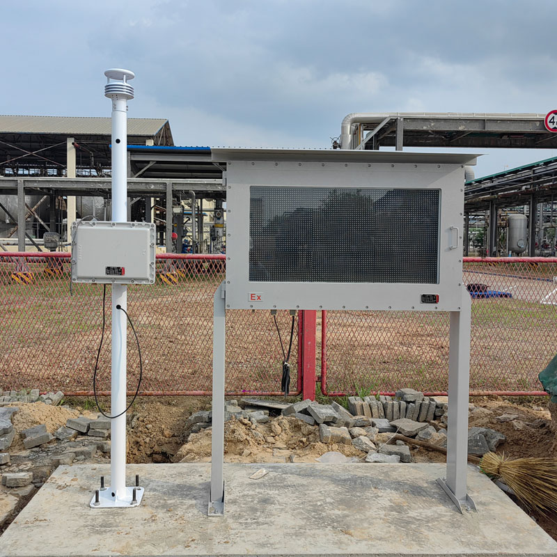
The lightning warning system is a fully digital electric field detection and lightning warning platform. Its core electric field detection structure is based on the principle of charge induction and developed using MEMS (Micro-Electro-Mechanical System) technology. There are no movable mechanical parts such as motors, which are prone to wear, and it has outstanding advantages such as small size, low power consumption, high reliability, and ease of integration. This system uses electric field differentiation combined with threshold optimization to improve the accuracy of lightning warning algorithms. Compared with the conventional threshold method, it significantly avoids false positives caused by human interference (rainy days/gales/snowy days/dust), further improving the accuracy of the warning. The lightning warning system has a high degree of accuracy in warning, is easy to network, and is convenient to install. It mainly meets the application needs of atmospheric electric field detection and local short-term lightning warning in the fields of aerospace defense, meteorology, petrochemicals, power grids, scenic spots, mines, oil depots, military, etc.
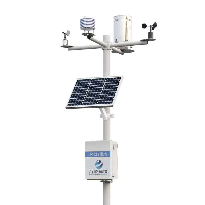
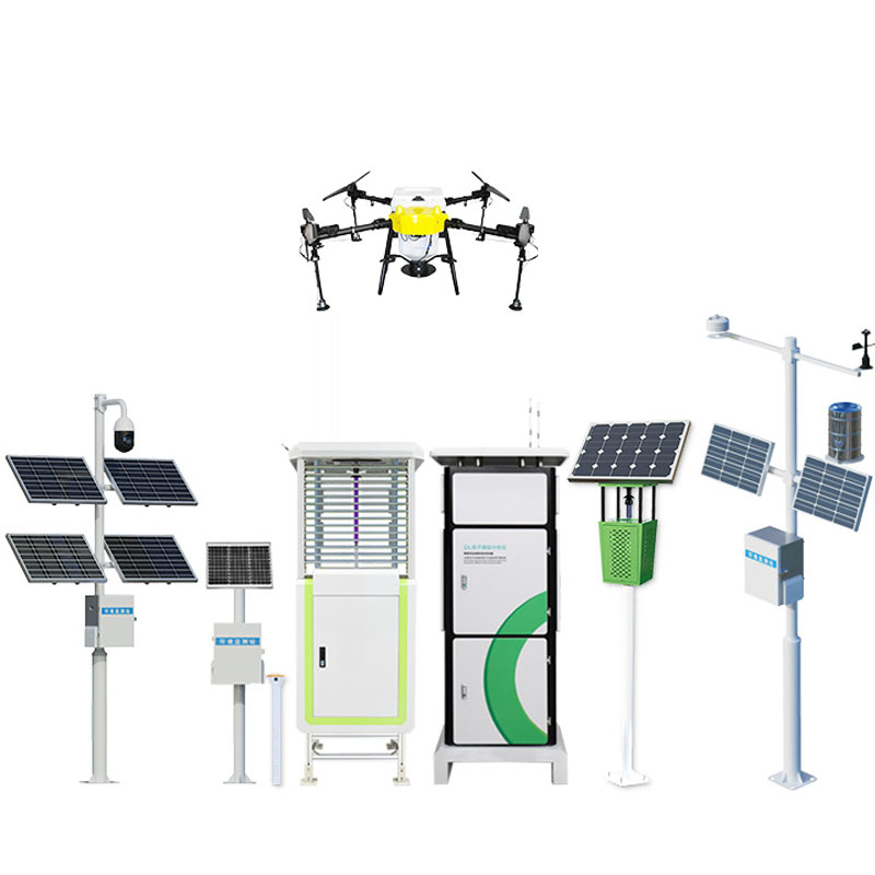
Second, product composition
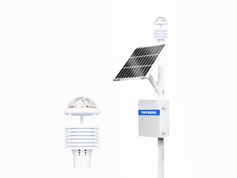
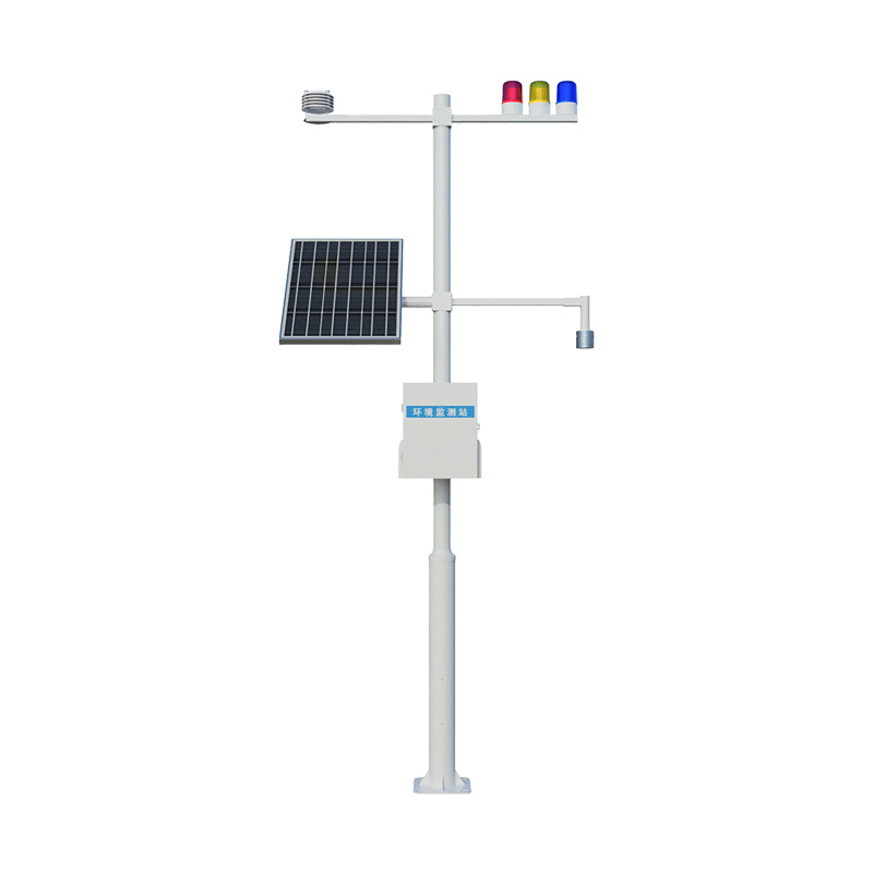
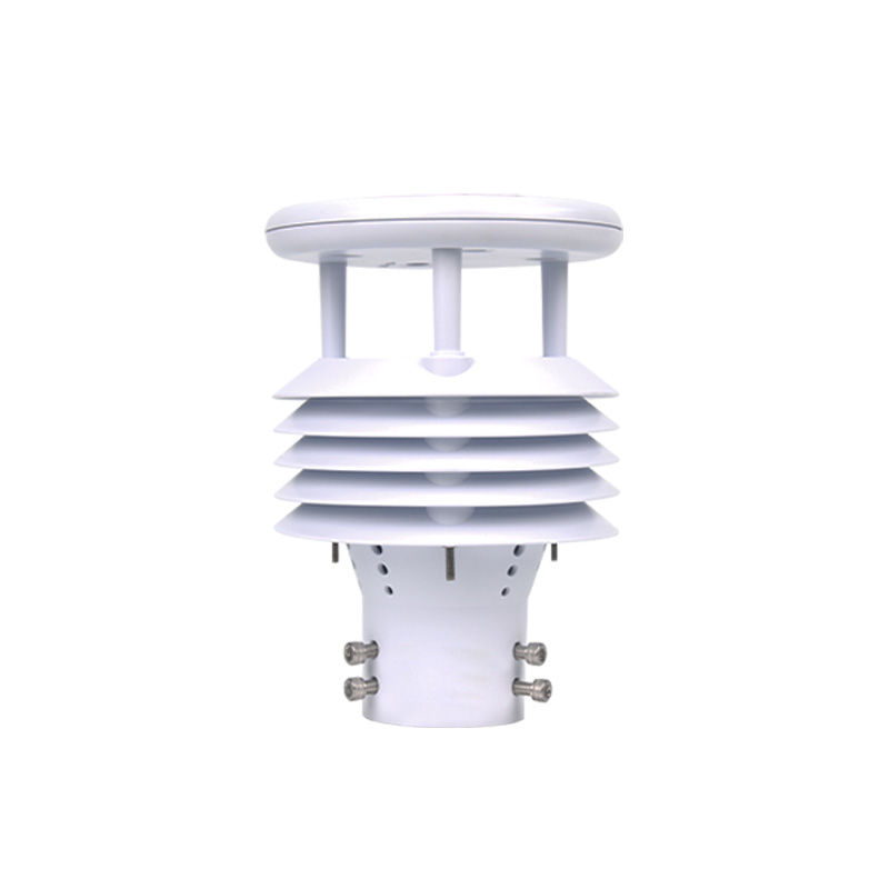
1. Lightning warning probe
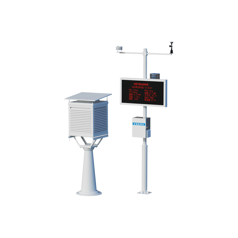
2. Data processing host
3. Solar power supply system
4. Lightning protection system
5. Surge system
6. Earthing system
7. Air temperature, humidity, atmospheric pressure sensor
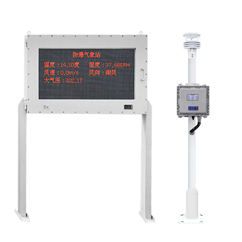
8. Audible and visual alarm 3rd level
9. Cloud data query and real-time display
Three, product features
1. Users can connect the lightning warning system probe to the cloud server to achieve the purpose of remote monitoring.
2. Through the analysis of data, a more accurate judgment of the strength and polarity change of the thundercloud electrostatic field can be made.
3. This system can be connected to the audio-visual alarm system.
4. The system software has a complete network transmission function; the transmission of data fully conforms to the network protocol.
IV. Technical Parameters
| Device name | Lightning warning system |
| Electric field measurement range | -100kV/m~100kV/m |
| Discrimination | 0.1V/m |
| Accuracy | ±0.001%F.S |
| Detection range (radius) | 15KM |
| Weight of the whole machine | 36KG |
| Sensor weight | 710g |
| Input voltage | DC12V |
| Power consumption | 12VDC (2W@12V) (system) |
| Size | 105*78mm (sensor); 3m (vertical post bracket) |
| Working temperature | -10℃~60℃ (sensor); -40℃~80℃ (controller) |
| Deployment location (indoor/outdoor) | Outdoor |
| Stacking height | 2m (support) (sensor installation height 1.8m) |
| Management interface type | RS485-Modbus-RTU (sensor); RS485-json/RS485-Modbus-RTU (controller) |
| Alarm linkage (control) function | 3-level alert |
| Number and type of data interfaces | 3 Aviation connectors, 1. Power, 2. RS485-json, 3. RS485-Modbus-RTU |
| GPRS data traffic demand | 100M/Month |
| Data frequency of external transmission | 60s |
| Data communication protocol for external transmission (broadcast) | JSON |
5. Installation Precautions
1. The lightning warning probe should be installed on a sunny day.
2. Lightning warning probe should be installed outdoors without obstructions and without obstructions around it.
3. Shall not be installed at the exhaust outlet of the generator, near the telegraph pole and under the high-voltage line.
4. In abnormal conditions, the field strength and its test data may be disturbed when it rises from the ground, near the antenna mast or other equipment.
5. In the case of wired connection, it is not recommended that the distance between the outdoor electric field meter probe and the indoor host exceed 100 meters.
6. The equipment should be well grounded during use.
7. For more details, please consult our company.
8. Without prior notice, if there are any updates to the parameters, the technical interpretation rights belong to our company.
Six, installation steps
1. Take out the complete set of lightning warning system from the box.
2. Fix the bracket to the designated installation position with bolts.
3. The lightning rod (optional) is connected to the grounding wire at the top of the lightning rod, and the other end of the grounding wire is introduced from the inside of the support and led out from the bottom hole of the support. After the grounding electrode and other grounding devices are installed, the lightning rod grounding wire is connected.
4. The probe of the atmospheric electric field meter and the lines of the temperature, humidity, and pressure sensor are introduced from the inside of the bracket, led out from the hole in the middle of the bracket, and connected to the main control box. The expansion box is plug-in in the main control box.
5. Fix the solar panel to the bracket, and connect the solar wires by color to the photovoltaic controller.
7. Connect the battery to the photovoltaic controller
8. Connect the control wires of the tricolor sound and light alarm to the alarm control module one by one according to the wire color.
9. Contact after-sales service through the device number on the device box to obtain a login account.
10. Turn on the computer and log in to the cloud platform to view the data through the browser (Google or Huawei browser).
Product address:
http://www.qxhjjc.com/en/leidian/1599.html 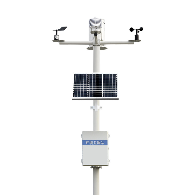


 Home
Home phone
phone Product Overview
 Contact Us